Operation modes
- LIN-CAN Gateway as LIN Master or LIN Slave
- LIN-Slave Emulation
- LIN-Master-Slave Emulation
- LIN-PC Interface
LIN CAN Bus Gateway
The LIN/ CAN Bus Gateway mode allows the transparent transmission of LIN messages to a CAN bus network. The device works as a LIN master or LIN slave. Received LIN messages are passed on to CAN and the LIN identifiers are translated into CAN identifiers. The LIN data is passed on via the CAN object. The device also provides a transmit function to LIN via CAN. For this, CAN identifiers are translated into LIN identifiers and, when requested by a LIN master are transmitted once in the LIN network. The data of the CAN object is stored in a buffer and then transmitted as LIN data. PC programmable translation tables, which are stored on the device, are available for the translation of the messages.
LIN Slave Emulation
The LIN slave mode provides a stand-alone LIN slave emulation. The device has a configurable transmission table. When a LIN header is received, the stored data is transmitted. The table is configurable by the PC and is stored in the flash memory of the device.
LIN Master Slave
As a LIN Master/Slave, the device works as a stand-alone LIN bus arbiter with LIN-Slave function. Here a configurable schedule list is available, which is processed cyclically. In addition to the bus arbiter function, a transmit function is also available in this mode via a configurable transmit list.
LIN PC Interface
In addition to the stand-alone modes, the LIN-CAN Gateway can also be operated via the serial interface as a PC interface. Here, for example, the device can be operated as a LIN-Slave where the LIN objects on the PC are available for monitoring. The transmit table can be modified interactively. In addition, the LIN-Master function is available where the bus arbiter function can be triggered from the PC. With these functions, a PC-supported simulation of LIN-Slave or -Master devices is possible.
All modes can be configured via PC. The configuration values are stored in the FLASH Memory of the device and can be read out by the PC.
| Technical data | |
| Microcontroller | Fujitsu MB90F543 |
| Interfaces | 1x CAN ISO 11898-2 High-Speed, |
| 1x CAN ISO 11898-3 Low-Speed, | |
| 1x LIN, | |
| 1x RS232 | |
| Memory extension | 128 kByte Flash, 516 kByte RAM |
| Extras | Automotive: Configurable Sleep mode with Wake up via CAN, LIN or RS232 |
| Industrial: - | |
| Power supply | Automotive: 7 V ... 16 V DC, 1.5 W |
| Industrial: 10 V ... 32 V DC, 1.5 W | |
| Temperature range | -20 ºC ... +70 ºC |
| Certification | CE |
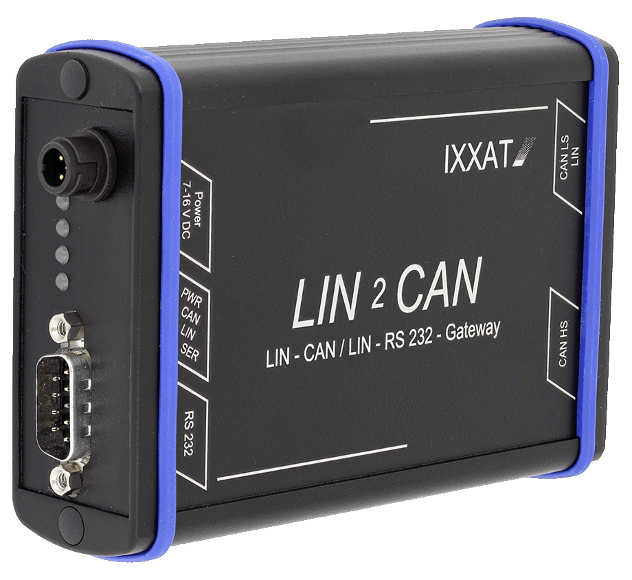
| Housing | Robust metal housing approx. 100 x 85 x 32 mm |
| Contents of delivery |
| - LIN2CAN |
| - Configuration software for Windows™ |
| - Configuration cable (RS-232) |
| - Power supply cable |
| - User Manual |


