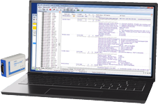
canAnalyser
Multi channel tool for CAN, CAN-FD and LIN
The CAN Analyser is a powerful and versatile analysis tool. The standard version is designed for the development, testing and maintenance of multiple CAN, CAN-FD or LIN channels at the same time, the Lite variant is suitable for single channel.
Highlights
- Supports CAN, CAN-FD and LIN
- Online viewing of all bus traffic
- Sending of one-off messages or message sequences
- Simultaneous access to up to 64 CAN networks
- Recording of CAN messages with miscellaneous trigger conditions
- Multi-start of modules allows the simultaneous analysis of different functions
- Statistical analysis of message traffic, such as bus load
- Generation of commandcontrolled sequences
- Easily expandable by including .NET extensions
- Support of CANdb, FIBEX 3 and DIM databases for interpretation and sending of process parameters
- Graphical representation of message content
- Processing of scripts
- Additional protocol modules available for CANopen, J1939 and DeviceNet
Configuration and use
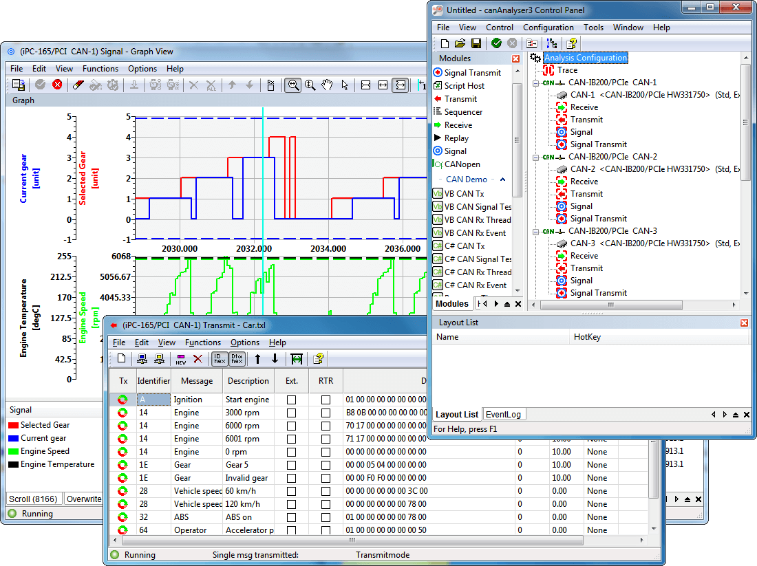
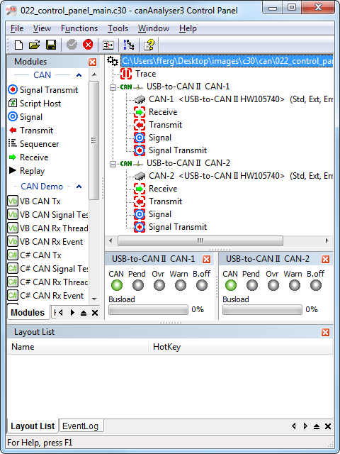
The control panel of the canAnalyser is the central element for configuration. Supported by a Wizard, the required CAN interface is selected and the CAN controller on the board is configured. It also defines which function modules are assigned to the CAN controllers. The configuration is clearly displayed in the form of a tree and the module assignment occurs intuitively by means of drag and drop. Each CAN bus can be assigned a database.
Receiving and displaying CAN messages (Receive Module)
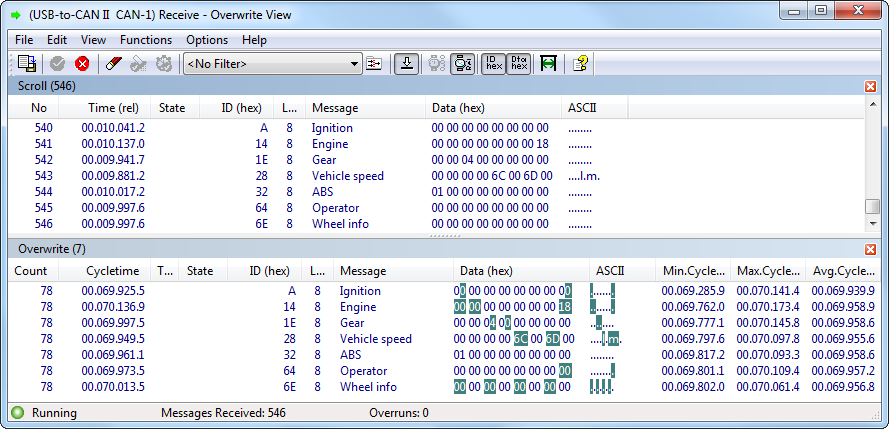
The CAN messages transmitted on the CAN bus can be displayed online in different ways. Either all messages or only certain ones, selected via an adjustable filter, are displayed. Messages can be displayed in two ways. In scroll mode, the messages are displayed together with the time of reception one after the other in a list. This form of display is particularly suitable for monitoring message sequences. On the other hand, in the overwrite mode the messages received are listed according to the identifier and permanently overwritten with the incoming data. Each message is assigned a counter, which displays the commonness of its transmission. Here the altered byte is highlighted in color. With the additional cycle time monitoring, the regularity of reception is observed.
For further monitoring of certain message groups, the receive module can be started multiple times, where each instance can display one section of the CAN data flow.
Transmission of CAN-messages (Transmit Module)
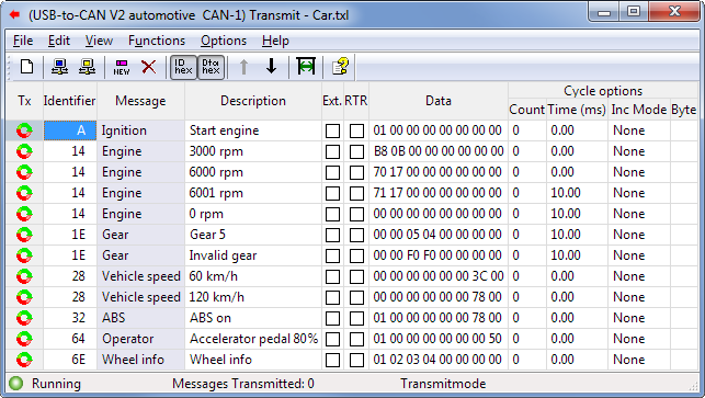
Messages to be transmitted can be arranged by the user in a message table. Individual entries from this table can be transmitted once or cyclically. The table contains both the definition of the message (identifier, data bytes, RTR bit) and a description of the message. The data entry can be either decimal or hexadecimal. For messages to be transmitted cyclically, cycle times of 250 us (depending on the used hardware) to 100 s can be specified. In cyclic transmission mode, identifiers or data contents can be incremented automatically.
Recording CAN messages (Trace Module)
With the trace module all received messages and error frames are recorded directly onto the hard disk. The recording can be started and stopped via the trace control. In addition, trigger conditions for starting and stopping as well as filters for the CAN messages to be recorded can be defined for each bus. A trace can be viewed at any time and can be reloaded into a system offline for analysis by specifically configured analysis modules, or, online with the aid of the sequence module (limited number of messages).
Play-back of Trace Files (Replay Module)
The Replay Module enables the play-back of trace files. In online mode the messages can be send to the CAN network and received via self reception, in offline mode the messages can be distributed to the connected canAnalyser modules.
Transmitting message sequences (Sequencer Module)
During the development of CAN devices, functions, protocols and complete systems situations can be tested by transmitting message sequences. Unavailable devices can also be simulated. The message sequences are created with a few easy to learn commands (such as transmitting a message, waiting for a message, pause with specified duration, repeat, user input) via an integrated editor and then executed at the push of a button.
Symbolic interpretation and display of transmitted process variables (Signal Module)
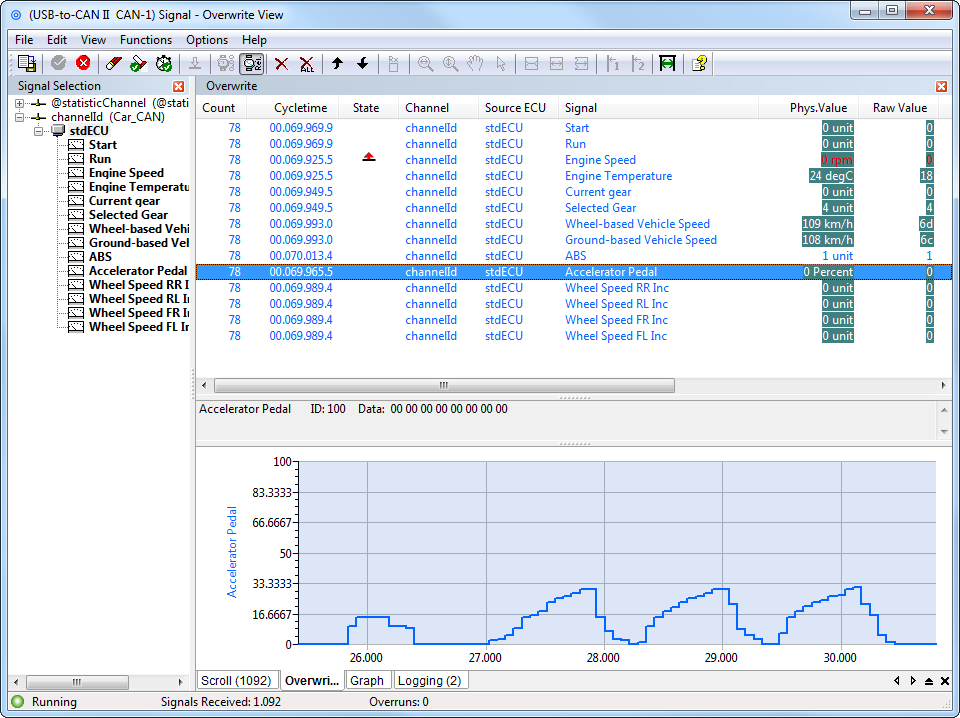
Beyond the display of the receive module, not only is the identifier of a CAN message with a symbolic name displayed, but the complete contents of the message are also extracted and displayed as signals (physical values) based on the interpretation rules stored in the database.
Whether in scroll mode or in overwrite mode, the signals contained in a CAN message can be displayed with the signal module. Messages and signals can be activated and deactivated individually, i.e., excluded from interpretation.
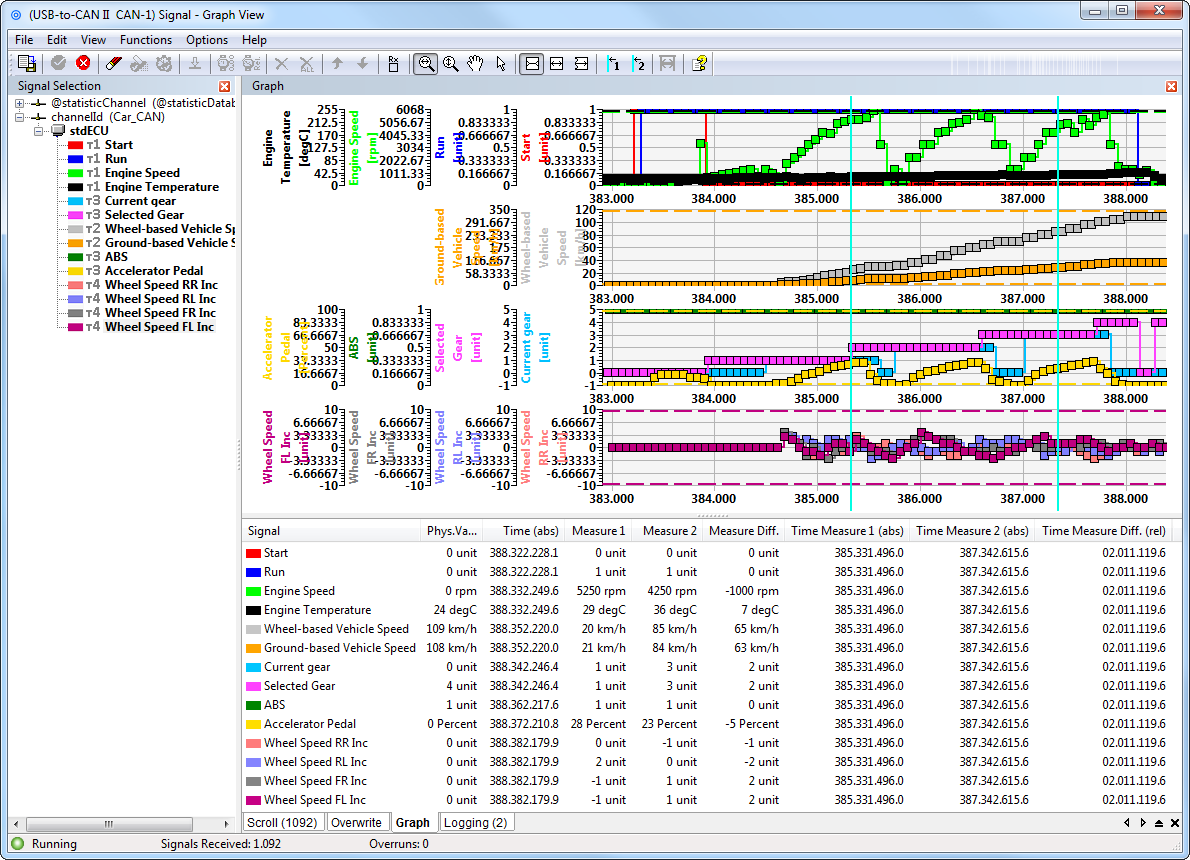
Data contents of CAN messages are displayed in the graphic module in a window over the time axis. The information to be displayed, such as name and unit is automatically taken from the database allocated to a CAN bus. The data is displayed in real time, where a maximum of 16 signals per graphic window are distributed over up to 4 time axes. In addition, the current value of a signal is displayed numerically. With the aid of a metering bar, specific values can be determined and evaluations carried out.
Scripting Host
The Scripting Host provides a powerful interface that combines the advantages of graphic Windows programs with the flexibility of scripts. By using the Scripting Host the canAnalyser can be quickly and easily adapted to specific measuring and analysis tasks. This allows the user to simulate devices and protocols or to test existing devices in the simulated restbus and to put them into operation. Specific test environments can be easily created using any Windows interface components. The Scripting Host supports the standard script languages C# and Visual Basic .NET. The incorporation of DLLs also enables the integration of further modules.
Programmability
Due to the open programming interface, the canAnalyser can be extended by the user's own modules or user interfaces. With common Windows development systems (e.g. Visual Studio.NET), new, independent modules can be developed and added to the canAnalyser. It is possible for users to create interfaces for their systems or for certain devices or tools with system specific analysis functions.
Editor for the project databases
The basis for the interpretation and symbolic display of the data transmitted in the CAN message is the project database. In this, a CAN message is first assigned a name according to its identifier.
| Hardware requirements | |
| - PC with Windows XP, Vista, Win 7, Win 8 or Win 10 (32/64 bit) | |
| - Ixxat CAN interface and VCI driver | |
| - Ixxat CAN-FD interface and VCI driver for CAN-FD | |
| - Ixxat CAN-interface with LIN-interface and VCI driver for LIN | |
| Contents of delivery |
| - Software as single user license, consisting of: Control Panel, Receive module, Transmit module, Trace module, Replay module, Signal module, Signal transmit module, Sequencer module en Scripting host module |
| - Database editor |
| - Sample programs for using the programming interface |
| - User Manual |
| - USB license key (One USB 2.0 connection required) |
Part number(s)
Bundles with protocol module and USB-to-CAN interface
canAnalyser 3 + CANopen Module + USB-to-CAN V2 Professional
canAnalyser 3 + DeviceNet Module + USB-to-CAN V2 Professional
canAnalyser 3 + SAE J1939 Module + USB-to-CAN V2 Professional
Modules
CANopen, DeviceNet and J1939 modules can be added later to the canAnalyser 3. An upgrade from canAnalyser 2.x to 3.0 requires applicable modules to be upgraded also. Ask for the possibilities!


